Coming together

Coming together
Getting close to paint

Monday, May 28, 2012

Not so Amish body raising

Hot day today in St Louis, what better time to work outside?  With the frame done, engine mounted, and steering sorted, it's time to find out how the body fits.  With help from a half dozen friends (Kurt, Amanda, Matt, Rob, and Scott) it felt a bit like an Amish barn raising with no tools, although I guess they wouldn't touch cars, so it's really nothing like that.  Thankfully a simple job with six people it probably took less than a minute. 

Here is the frame sideways in the garage, with the body directly behind.  Close fit, but it does fit sideways in the garage. Many hands makes light work lifting the body up and onto the frame.  Likely we will have to do this a couple more times, so it's good to know it doesn't weigh much even with the windshield and backlight still in.


 Here are a few pictures of the fit around the engine and transmission.  The body needs to slide forward about an inch (see the second picture below), which will tighten up the big gap between the motor and firewall.  It should sit just about right with the body in the correct position.  The top of the transmission is hitting just a little, so once that is clearanced the body will easily move in to position. It's exciting for me just to see the body back on the frame, even if just for a few days. Progress!

Next time, remember to put the computer forward on top of the motor.

 Lots of clearance for the floor and firewall to the header.  I wish the clearance to the frame was this good.  Probably still need some good heat shielding around the catalytic convertors, but that is a long way off to worry about.
 Here you can see where the firewall hits the transmission.  We left plenty of metal so it should be an easy job to cut more out, and use the new floorpans.  We may need to add about 4" to the middle to get the necessary clearance.  It won't hurt to have a little extra either.
 Here is where the shifter sits.  I was guessing where the seat goes, and I think it will be in a very comfortable position, not too far back in the chassis.  Plenty of room around the driveshaft as well.  More than anything it is a bit unnerving to know what is spinning just the other side of a thin piece of sheet metal.
 It's a little easier to see in this picture where the shifter needs to move to.  Look where the two ridges are at the front of the floor, and where they are in the old floor plan on top, 4-5" back from the original position.  I think we will use the original floor pan around the shifter to fill the gap, which just leaves a small strip in front to fill.  I don't think it will be a bad job, but we have to mark everything, then take the body off again to cut and weld the panel in.  Hopefully I can find enough people around to test fit the panels before we weld them in solid and mount the body to send everything back to the body shop. Seems like a lot of extra work, but the more test fitting, the better the final product will be.

Sunday, May 13, 2012

Steering clearance at last, oil pan v. 3

 Third times a charm, right?  We started with an LH8 oil pan (used on Hummer, etc) that fit great over the frame until I tried to fit the tie rods.  The tie rods hit the pan pretty solidly, which would be a bad thing if you cranked the wheel and cracked open the oil pan.  Think catastrophic engine failure.  Thankfully, Mast Motorsports just came out with a case oil pan that addresses this problem.  There were other cheaper options, but none have the oil filter mounted on the pan.  My goal is to stay closer to stock, so I didn't like these options.  Mast is pricey, but looked like it would work. The LH8 pan is in the back in the picture below, Mast at the bottom.  They had to put reliefs in the oil pan to allow for the oil tube and the windage tray.  It looks like every attempt was made to make the front of the pan as skinny as possible.
 The LH8 pan is on the right below.  The other point to notice is the rear of the pan isn't as deep on the Mast pan compared to the LH8.  Why does this matter?
Well, compare the next two pictures. First is with the LH8 pan, second is with the Mast pan.  See the LH8 pan sticking a couple inches below the crossmember?  If you hit a speedbump or hole in the pavement, the first think you will hit is the oil pan.  Cast aluminum doesn't bend when hit, so this could result in total loss of oil if it gets hit.  The Mast pan solved this problem as well.  I HATE buying parts twice, so learn from my mistake and buy the Mast pan first.  I do have an LH8 pan for sale though...

 Even with the Mast pan, we had to shim the motor mounts to get complete clearance with the tie rod ends and the oil pan.  We used three skinny washers between the motor mount and the block to get clearance.  We probably could have got away with one or two; with three there is a good 1/8" clearance  between the oil pan and tie rod ends.  I figure if anything settles or moves around the extra clearance is good insurance, so we left all three washers in place. Carquest built a high pressure power steering hose for me to connect the Camaro pump to the Jeep Grand Cherokee box.  It's a simple part, but critical and looks like it was designed to fit.  Maybe I'm easily amused, but there is a lot of satisfaction to get these custom parts to fit and look like they aren't custom.  Next step for me is to mock the body on the frame, and finish the floor around the shifter. We're not done with the custom bits by a long shot, but if the steering shaft fits with the headers, we will be in very good shape with mounting the LS1.

Sunday, April 22, 2012

Frankenstein power steering

This week I finally had most of the parts to get the power steering installed.  It struck me as I was ordering parts what a frankenstein setup this is - 2004 GTO motor, 2001 Firebird pump, 1998 Cherokee steering box, 1965 Chevelle steering parts.  Somehow it seems to be working together.  I purchased the bracket from Speedway motors that get the alternator up and out of the way of the steering box (see the last picture).  It also moves the steering pump to the top of the motor.  My first surprise was to find that the GTO pump is different.

The bolt pattern is wider on the GTO pump, and the pulley is smaller and steel with an external reservoir.  The Camaro/Firebird pump has the reservoir mounted, and a larger composite pulley.  Note the composite pulley doesn't have the holes to remove the bolts, so I had to get a puller to clean up the Firebird part and put the right bolts on.  Thankfully after this the Firebird pump does bolt directly to the Speedway bracket, and it puts the pulley in alignment with the alternator and the crank.  

 In the picture above, GTO part is on the left, Firebird part is on the right. Below, the GTO pulley is on top, and the Firebird part on the bottom.  I think either pulley might work; I went with the composite pulley since it matched the pump and was a little lighter weight than the GTO.

The Speedway bracket came with a new belt, but it was way to short to work with or without the idler pulley (up and to the right of the crank pulley).  I thought that the idler pulley would help keep the belt from wobbling, so I used the stock GTO serpentine belt (new of course).  It fits great, even with the alternator and power steering in a completely different orientation.  It's hard to see in this picture the bracket holding the idler pulley that used to also hold the alternator.  I cut off the from two arms that held the alternator low by the power steering box since they served no purpose.  I have to admit it felt great to get this together; I was worried with all of the different models and years that this would not work, but somehow it all comes together.  How anyone figured this out I don't know, but thanks to the internet for providing the information!  I do have to lengthen the alternator wires about six inches to get them to fit, and have ordered custom power steering lines to connect the pump to the steering box.  Maybe someday I'll get shiny parts to make this all pretty, but my focus now is to move forward.  The pitman arm is on backorder; once this arrives the steering should be done up to the column! Next I need to start thinking about how to route the brake lines...


Sunday, April 8, 2012

Testing my patience.

This has been a tough week for me, partly because I get frustrated easily by parts that don't fit. Not a good trait when building a custom pro-touring car.  Perhaps a little odd as well since I do like a challenge.  Tomorrow there is a car show in Forest Park for only original cars, I guess for people that like to take the easy route.  This week I was somewhat wishing I had done that, but I'm sure it will be worth the pain some day.

Starting off this week is something that did work well.  I ordered a custom driveshaft from Brent Crownover at Driveshaft Specialist Incorporated in San Antonio.  We talked through my plans for the Chevelle, and he recommended a 3.5" aluminum driveshaft.  His price was very reasonable, they shipped it out in less than a week, and you can see it fit perfect. Obviously I can't say how it drives yet, but based on my interaction I would definitely recommend them if you need a custom driveshaft. It should be plenty strong and with less weight spin smoothly at highway speed.

 Next is on to the steering.  I've read lots of different reports on what fits and what doesn't, so I wasn't quite sure how this was going to go.  I went with a pretty stock setup, only changing the steering box to a 93-98 Jeep Grand Cherokee.  It's a direct bolt up to the frame, so that part is good.  The steering linkage runs into the exhaust headers and alternator, but more on that later. With difference in the oil pans, motor adapter plates, sway bars, and steering parts, there are many combinations you could end up with.  My kit uses an Addco sway bar that comes very close to the idler arm.
With the box in place, I pulled off the Jeep pitman arm, and tried to fit up my new Chevelle part.  Here was the first problem - CPP sent a manual steering box Pitman arm; I need a power steering box part.  The difference is the hole attached to the box is a different size.  Jill says the tech on the phone was arguing with her until she read the part number back to them.  I guess they didn't believe that they had shipped the wrong part.  Hopefully when we get the correct power steering pitman arm it will fit without issues.
 All of the steering parts are new from CPP.  The tie rod ends are much beefier than original.  Obviously I'm guessing on alignment (probably could measure front and back of wheels and get somewhere close); with the new parts it appears that they will be right at the edge of being able to adjust properly to get the toe in correct.
 The sway bar came as part of the pro-touring kit from CPP and is an Addco part.  It is much larger than the factor bar, and looks to have lots of universal parts.  The bar itself appears to be of high quality.
The holes in the brackets for the sway bar needed drilled out so they would fit the factory holes in the frame.  Also Addco did not send bolts, so I had to make another stop for new bolts.  It felt cheap that they would not include new bolts. I powdercoated the gold cadmium plated brackets to cover the grinding, and they looked ugly. Much better in all black, although I may need to go back and touch up all of the bolts with black later.

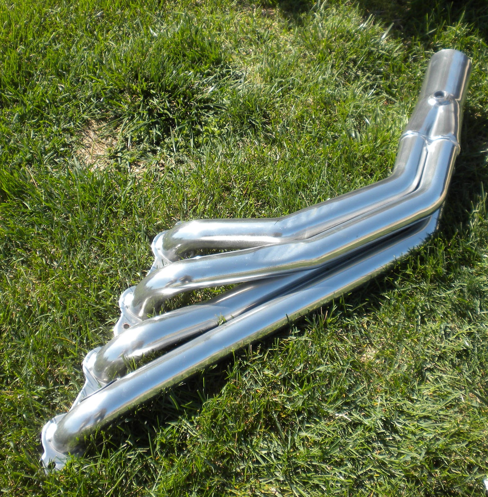
 With the steering in place, next step was the headers.  I purchased a set of Dougs Headers (from Petronix) specifically made for this swap, so I'm thinking no problem fitting them.  Well, the drivers side appears to tuck nicely and should allow the steering linkage to fit properly with the LS1.  That part is good.  The quality of the headers is also excellent.  Problem is now on the passenger side, where the header hits the bellhousing and the frame.  I see Holley now makes a cast header that fits nicely to the block.  If I had a chance to do it over, I think I would have purchased the Holley header because it looks like it would save some of these headaches. I cannot recommend Doug's Headers if you are doing this swap. Hopefully if any car guys are reading this you can give me some tips or let me know how much of a problem these will be.

To get the drivers side header to fit, I used a large socket and a 3lb hammer to dimple the tubes.  In the picture you can see what needed to be done.  The right side needed pretty much the same treatment.  Thankfully the ceramic coating is very tough and took the 'adjustment' well without cracking.

The next three pictures show the final fit.  There is probably 1-2 mm at the narrowest point.  I'm a little worried as the motor flexes under acceleration that it will bump, but hope that under normal driving there isn't enough vibration to cause a problem. There is tons of room on the left side that the header could have been made tighter to the block. There is no excuse for a design this bad that I can see.  I also don't like that the O2 sensor bung faces outwards.  There is plenty of room on the inside by the transmission, and it would have made a much cleaner look.  Yes, it is under the car, but still I want everything nice and tidy.  Sure, I'll admit I'm a perfectionist.  They show under car cameras at Barrett Jackson (not that the Chevelle would ever be there), so people do care about the underneath.


Okay, on to the right side.  The header hits the bellhousing by the starter.  There is lots of extra meat here, so a few minutes with a grinder and...


 ...this is what I came up with. Sharp eyes will notice the piece I removed at the bottom of the picture.  Looking at a few forums this seems to be a common modification, so plenty of space here.  Tip for anyone trying this - install the starter now.  Don't so it after putting the header on like the direction say.  It will go on, but it's not fun.

 And again the final result after lots of test fitting and pounding.  You can see on the bellhousing side there is now plenty of room.  The starter solenoid is a little close for my comfort, so hopefully it is designed to take the heat.  If I have any hot start issues later, I'll know why.
 The starter wiring needs to go towards the front of the car, underneath the header.  It looks obvious now where it should go, but trust me as it's going together sometimes obvious isn't quite what you think.

The dipstick goes back in the middle of the header. So, here comes the final problem - only six of the eight plug wires fit with the header.  The wires have an aluminum shield to keep them safe from the heat, and on the second plug back from the front on both sides, it hits.  If it were flexible, all would be good, but last I checked there isn't a lot of flexibility in aluminum tubing.  Any suggestions?  Not sure how I'm going to solve this problem, but I figure that is for another day.  New plugs first, since it will never be easier to change them.
 And the final product.  Driver side too close to frame, passenger side is close on both sides, two plug wires don't fit.  It doesn't look like there is any chance they will hit the floor as many report with other headers, so that should be good.  They should make these a little lower to the ground so they would easily go under the transmission crossmember.  I guess whomever makes the exhaust will get to deal with this. Notice plenty of space for O2 sensors on the inside, but bungs to the outside. Man the frame rails on an A-body are narrow! Hopefully next week finish up the steering and on to trying to make the floor fit.


Sunday, March 25, 2012

Got the frame back from paint

The frame came back a couple weeks ago - I was out of town so Jill and the shop guys had to push it into the garage in the pouring rain.  Hopefully the only time it sees rain.  I finally made it out today to check out the work Jack and his crew at Specialized Collision have done. I won't say more about the cost other than it was expensive, but everything builds off the top of a solid frame.  The body work is cosmetic for the most part, the frame and suspension have to function well.  I had the frame boxed were it was only c-channel from the factory.  The first few pictures are of the boxing in the rear section (around the trunk/gas tank).  You can't tell that it wasn't originally this way; the welding makes the factory welds look horrible.  In fact, they are pretty much invisible.


 The next few shots are of the rear axle installed with the new disc brakes, suspension, and completely rebuilt original 12-bolt rear axle with 3.07 gears.  The kit was from Classic Performance Products.  Parts generally fit okay, except the pre-bent brake lines that were no where near correct.  The emergency brake cables are also a little long, so I will need to figure out that at a later date.
 The aluminum shocks and differential cover are really just bling, but they look good against all of the black.  The kit adds a rear sway bar, that is not available on a '65 Chevelle.  This should help, along with all of the new suspension, with the handling since muscle cars weren't known for turning corners.


 You can see the boxing in the center sections in the next few pictures.  Again perfect welds you would not know there were there.  The shop added the end plates to the transmission crossmember and set the pinion angle on the transmission.  They reused the original crossmember by my request, to help keep the original look as much as possible.

 Notice the factory welding apparent at the seam to the left of the picture, and compare that to the seam at the right.  Looks like one solid boxed piece now.  I've read that the open frame is like a wet noodle, helps with the ride by flexing over bumps, but is terrible for handling.


 And a few shots of the front suspension.  I still need to install the sway bar and the steering arms, but that will have to wait for paint and more free time.  The ride height was set by the shop pretty low.  I'm sure it will look good, but I plan to raise it to close to the highest setting to make sure we have plenty of ground clearance.  Last thing we need to to scrape the frame or bottom out on the oil pan.


And just so you remember what we started with, here is a picture during disassembly before:
 and after...  what a difference.  Better than original!